Valves and Plugs

These components allow the creation of countless hydraulic schemes.
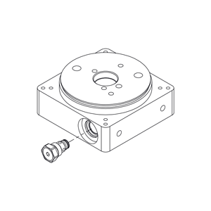
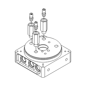
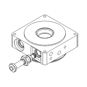
The mounting of both the valves and the plugs occurs through the cavities present on the central manifold of the hydraulic unit. The threads have been standardized, to allow for a quick replacement, in case of maintenance.
Choosing the right component is carried out by the technical department, that from the hydraulic diagram extrapolates the correct sequence of hydraulic components.
VMDC35 - Direct acting relief valve

The relief valve is designed to cover a wide pressure range, covering all claims arising from the performance of hydraulic pumps.
This valve results of fundamental importance in the preservation of all hydraulic components mounted on the hydraulic power pack.
The valve has direct command, and has an accurate pressure regulation through the rotation of a grain with hexagon socket, on the head of this one. A nut placed on the grain, ensures the stabilization of the setting pressure.

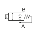
Relief valve hydraulic symbol
MAIN FEATURES

Max pressure: 320 bar
Max flow: 30 l/min
Weight: 0,16 Kg

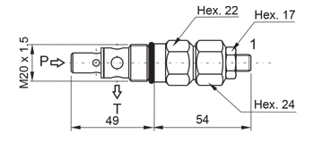
Relief valve M20x1,5 dimensions
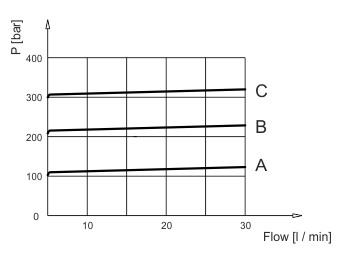
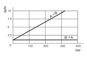
Relief valve M20x1,5 minimum setting pressure diagram
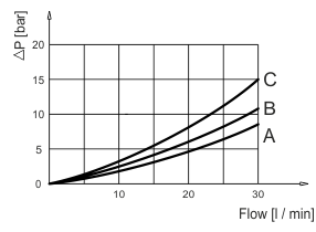
Relief valve M20x1,5 pressure vs flow diagram

Values measured on valve alone.

Pressure drop may change depending on fluid viscosity and temperature.

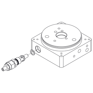
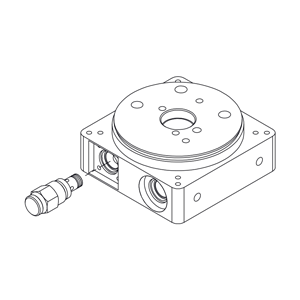
Relief valve M20x1,5
VMDC20 - Direct acting relief valve

The relief valve is designed to cover a wide pressure range, covering all claims arising from the performance of hydraulic pumps.
This valve results of fundamental importance in the preservation of all hydraulic components mounted on the hydraulic power pack.
The valve has direct command, and has an accurate pressure regulation through the rotation of a grain with hexagon socket, on the head of this one. A nut placed on the grain, ensures the stabilization of the setting pressure.

Relief valve hydraulic symbol
MAIN FEATURES

Max pressure: 350 bar
Max flow: 20 l/min
Weight: 0,10 Kg

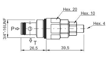
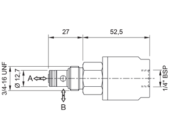
Relief valve 3/4"-16 UNF dimensions
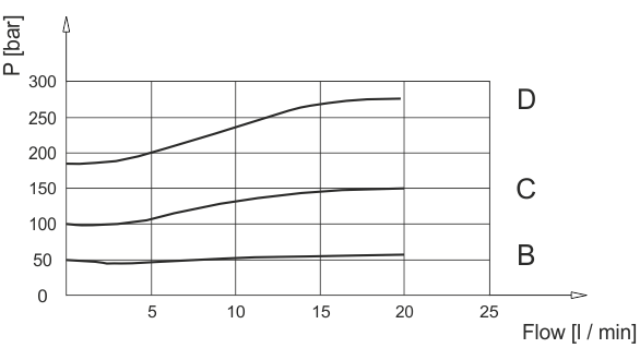
Relief valve 3/4"-16 UNF pressure vs flow diagram

For graphic reasons it is not shown the A curve.

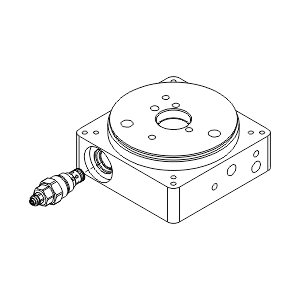
Relief valve 3/4"-16 UNF
VUC20 - Ball type check valve

The non-return valve, is used in all our hydraulic power packs, in order to preserve the pump from eventual pressures, returning from the hydraulic circuit.
Installation occurs in the cavity 3/4 “- 16 UNF, the use of this hydraulic valve, is present in almost all the hydraulic circuits.
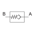
CHeck valve hydraulic symbol
MAIN FEATURES
Max pressure: 350 bar
Max flow: 25 l/min
Weight: 0,07 Kg
VUC20 dimension

Values measured on valve alone.

Pressure drop may change depending on fluid viscosity and temperature.

Check valve
VSC6 - Fixed compensated pressure throttle

This throttle can be employed as a compensated regulator on the exhaust.
The valve housing is foreseen on two different cavities, the wide range of calibrations can satisfy a high number of hydraulic circuits.
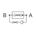
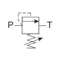
Fixed compensated pressure throttle hydraulic symbol
MAIN FEATURES

Max pressure: 250 bar
Max flow: 12 l/min
Weight: 0,06 Kg

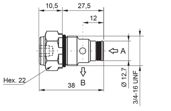
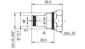
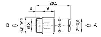
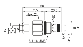
Fixed compensated pressure throttle dimensions
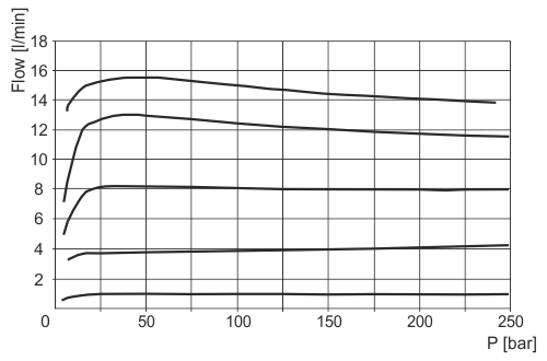
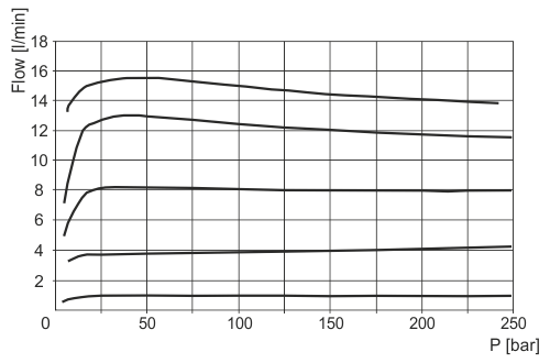
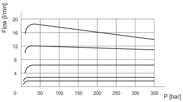
Fixed compensated pressure throttle diagram flow vs pressure
 Code
VSC60
VSC6A
VSC6B
 VSC6C
VSC6D
VSC6E
VSC6F
VSC6G
VSC6H
VSC6I
VSC6L
 Ø X [mm] closed 0,8 1 1,25 1,5 1,75 1,8 1,9 2 2,25 2,6

Nominal controlled flow, measured at 50bar.
Pressure drop may change depending on fluid viscosity and temperature.

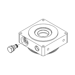
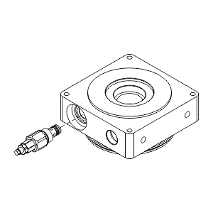
Fixed compensated pressure throttle
VSC - Fixed compensated pressure throttle

This throttle can be employed as a compensated regulator on the exhaust.
The valve housing is foreseen on two different cavities, the wide range of calibrations can satisfy a high number of hydraulic circuits.

Fixed compensated pressure throttle hydraulic symbol
MAIN FEATURES

Max pressure: 250 bar
Max flow: 12 l/min
Weight: 0,015 Kg

Fixed compensated pressure throttle
Fixed compensated pressure throttle diagram flow vs pressure
Code
VSC0100
VSC01A
VSC01B
VSC01C
VSC01D
VSC01E
VSC01F
VSC01G
VSC01H
VSC01I
VSC01L
ØX [mm] closed 1 1,2 1,5 1,7 1,9 2,1 2,3 2,5 2,8 3

Nominal controlled flow, measured at 50bar.

Pressure drop may change depending on fluid viscosity and temperature.

Fixed compensated pressure throttle with in-line mounting body
MSV - Pilot operated two-ways single locking solenoid valve

The uses of solenoid valves with cavity 3/4 “- 16 UNF, ensures the total interchangeability in case of maintenance.
Typical examples of application are the simple effect circuits and the commissioning pressure system.
The manually operated version, allows the drive of the solenoid valve even in the absence of tension.

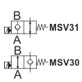
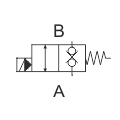
Pilot operated two-ways single locking solenoid valve hydraulic symbol
MAIN FEATURES

Max pressure: 350 bar
Max flow: 40 l/min
Weight: 0,27 Kg

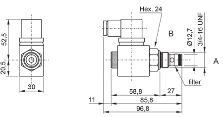
Pilot operated two-ways single locking solenoid valve
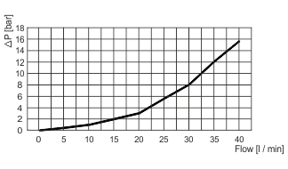
Pilot operated two-ways single locking solenoid valve pressure drop diagram
Valve type
Coil type
Power consumption
MSV3000 HDB + DC/RAC 18 W
MSV30E0 HDB + DC/RAC 18 W
MSV3100 HDB + DC/RAC 18 W
MSV31E0 HDB + DC/RAC 18 W

Values measured on valve alone.

Pressure drop may change depending on fluid viscosity and temperature.

Pilot operated two-ways single locking solenoid valve
MDV - Direct operated two-ways double locking solenoid valve

The uses of solenoid valves with cavity 3/4 “- 16 UNF, ensures the total interchangeability in case of maintenance.
Typical examples of application are the simple effect circuits and the commissioning pressure system.
The manually operated version, allows the drive of the solenoid valve even in the absence of tension.

Direct operated two-ways double locking solenoid valve hydraulic symbol
MAIN FEATURES

Max pressure: 250 bar
Max flow: 30 l/min
Weight: 0,35 Kg (with coil)

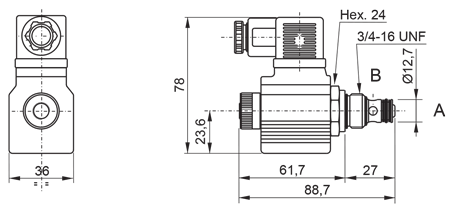
Direct operated two-ways double locking solenoid valve dimensions
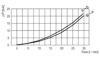
Direct operated two-ways double locking solenoid valve pressure drop diagram
Valve type
Coil type
Power consumption
MDV30E0 HDC + DC 22 W
Values measured on valve alone.
Pressure drop may change depending on fluid viscosity and temperature.
Direct operated two-ways double locking solenoid valve
CPE - Button operated two-ways directional valve
MAIN FEATURES

Max pressure: 320 bar
Max flow: 30 l/min
Weight: 0,12 Kg

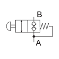
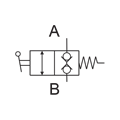
Hydraulic symbol button operated two-ways directional valve
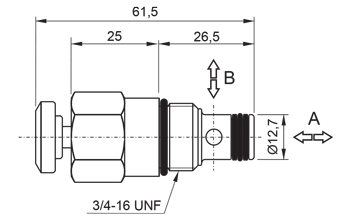
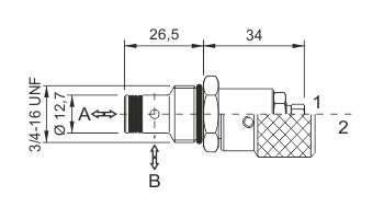
Button operated two-ways directional valve dimensions
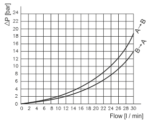
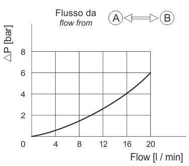
Button operated two-ways directional valve pressure drop diagram
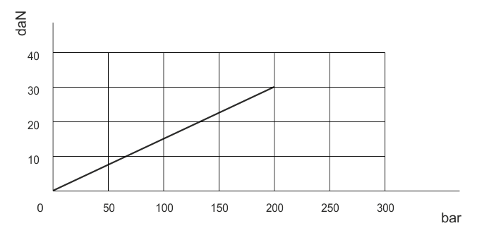
Button operated two-ways directional valve actuation force on the button

Values measured on valve alone.

Pressure drop may change depending on fluid viscosity and temperature.

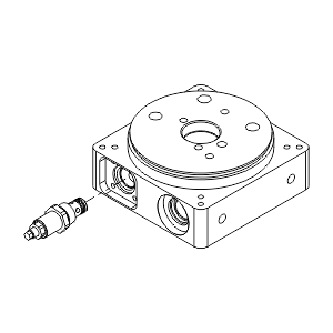
Button operated two-ways directional valve
VPN - Pneumatic opèerated two-ways directional cartridge valve
MAIN FEATURES

Max pressure: 350 bar
Max flow: 40 l/min
Weight: 0,16 Kg

Pneumatic operated two-ways directional valve hydraulic symbol
Pneumatic operated two-ways directional valve dimension
Pneumatic operated two-ways directional valve pressure drop diagram

Values measured on valve alone.

Pressure drop may change depending on fluid viscosity and temperature.

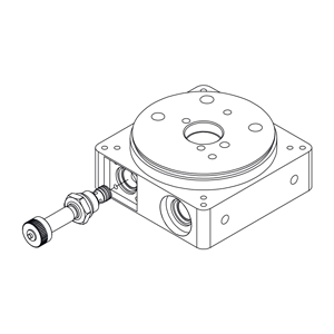
Pneumatic operated two-ways directional valve
CSC04 - Adjustable compensated flow control valve
MAIN FEATURES

Max pressure: 350 bar
Max flow: 18 l/min
Weight: 0,21 Kg

Adjustable compensated flow control valve hydraulic symbol
Adjustable compensated flow control valve dimensions
Adjustable compensated flow control valve pressure drop diagram
Code
CSC04A
CSC04B
CSC04C
CSC04D
CSC04E
CSC04F
CSC04G
ØX [mm] 0,9 1 1,3 1,5 1,7 2,2 2,8

Values measured on valve alone.

Pressure drop may change depending on fluid viscosity and temperature.

Adjustable compensated flow control valve
CSB - Bidirectional flow control valve
MAIN FEATURES

Max pressure: 300 bar
Max flow: 30 l/min
Weight: 0,09 Kg

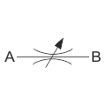
Bidirectional flow control valve hydraulic symbol
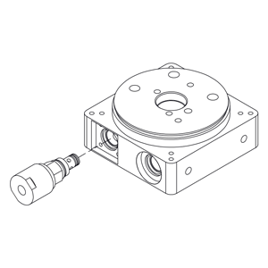
Bidirectional flow control valve
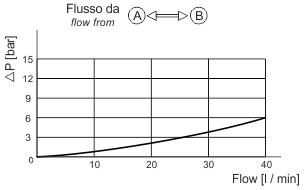
Bidirectional flow control valve pressure drop diagram

Values measured on valve alone.

Pressure drop may change depending on fluid viscosity and temperature.

Bidirectional flow control valve
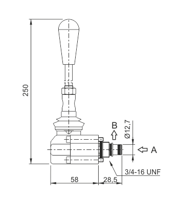
CM04L - Lever operated two-ways directional valve
MAIN FEATURES

Max pressure: 320 bar
Max flow: 25 l/min
Weight: 0,38 Kg

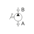
Hydraulic symbol lever operated two-ways directional valve
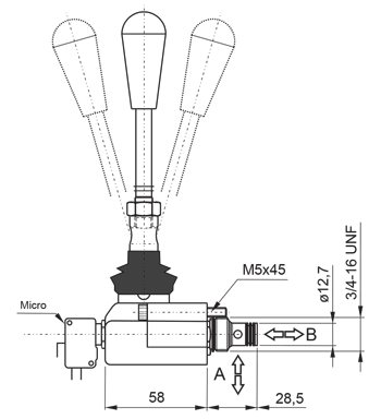
Lever operated two-ways directional valve dimension
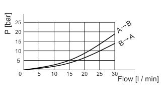
Lever operated two-ways directional valve pressure drop diagram

Values measured on valve alone.

Pressure drop may change depending on vuild viscosity and temperature.

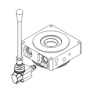
Lever operated two-ways directional valve
PM02 - Hand pump
MAIN FEATURES

Max pressure: 200 bar
Displacement: 2 cc/rev
Weight: 0,40 Kg

Hand pump hydraulic symbol
Hand pump dimensions
Hand pump acting forces diagram

Values measured on valve alone.

Pressure drop may change depending on vuild viscosity and temperature.

Hand pump
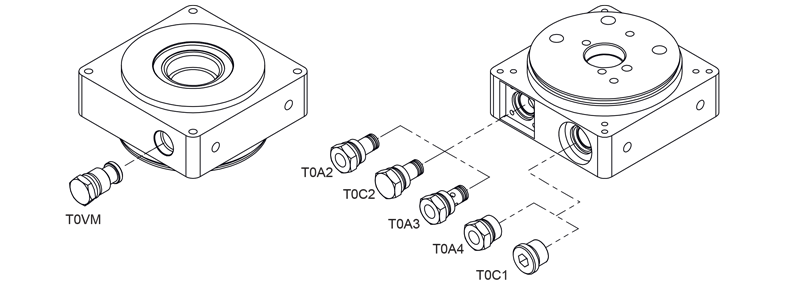
Function plugs

The choice of designing special plugs arises from the need to ensure the highest flexibility of the central manifold and adapt to as many as possible applications in hydraulics.

Functional plugs