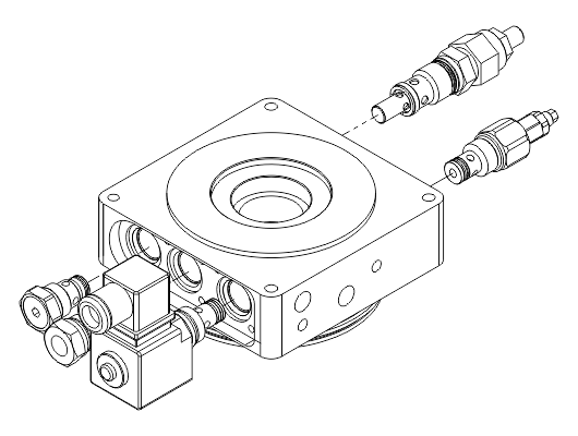
The central manifold is the heart of the mini power pack and it is for this reason that special care and deep study have been devoted to this component.
All the central manifolds are dimensionally tested.


The central manifold is the heart of the mini power pack and it is for this reason that special care and deep study have been devoted to this component.
All the central manifolds are dimensionally tested.
This central manifold is provided with two cavities that allow, if required in the hydraulic diagram, to accommodate both the pressure relief valve that check valve.
With this configuration it’s possible to realize simple hydraulic circuits, if the mini power pack has no blocks of the BL series, and more articulated, in the case of use of the latter, which allow modularly to be able to add a wide range of valves and solenoid valves.

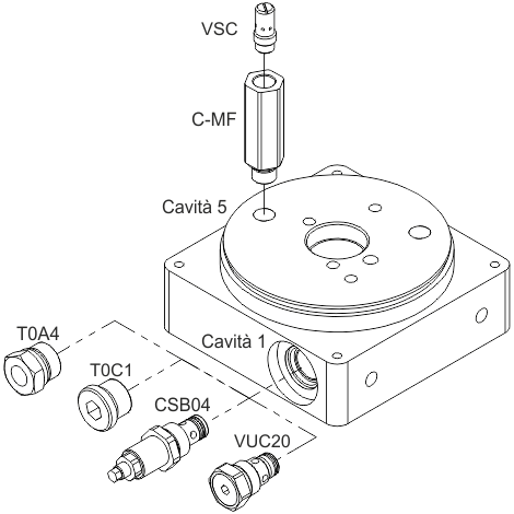
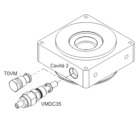
On this kind of central manifold is possible to mount the following valves:
Cavity 1: VUC20, T0C1, T0A4, CSB04
Cavity 2: VMDC35, T0VM
Cavity 5: VSC
The central manifold not presents any sharp edge, all the corners were rounded, to prevent possible injury during the assembly of the manifold. The outer surface also reflects strict choices of roughness, presenting glossy and pleasant appearance.
To assemble the components on the G02, please refer to the installation instructions of the valves and solenoid cartridge, shown in the catalogue.
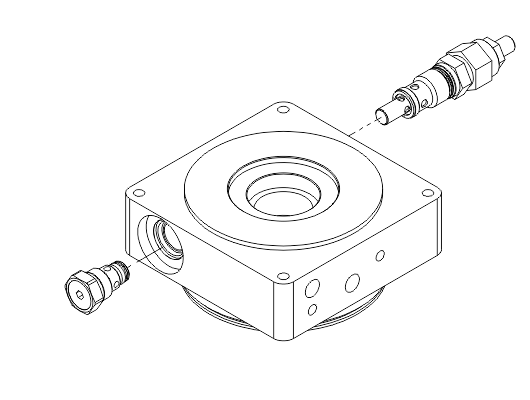
This central manifold is provided with three cavities that allow, if required in the hydraulic diagram, to accommodate both the pressure relief valve that check valve, that a derived solenoid valve.
With this configuration it’s possible to realize simple hydraulic circuits, if the mini power pack has no blocks of the BL series, and more articulated, in the case of use of the latter, which allow modularly to be able to add a wide range of valves and solenoid valves.

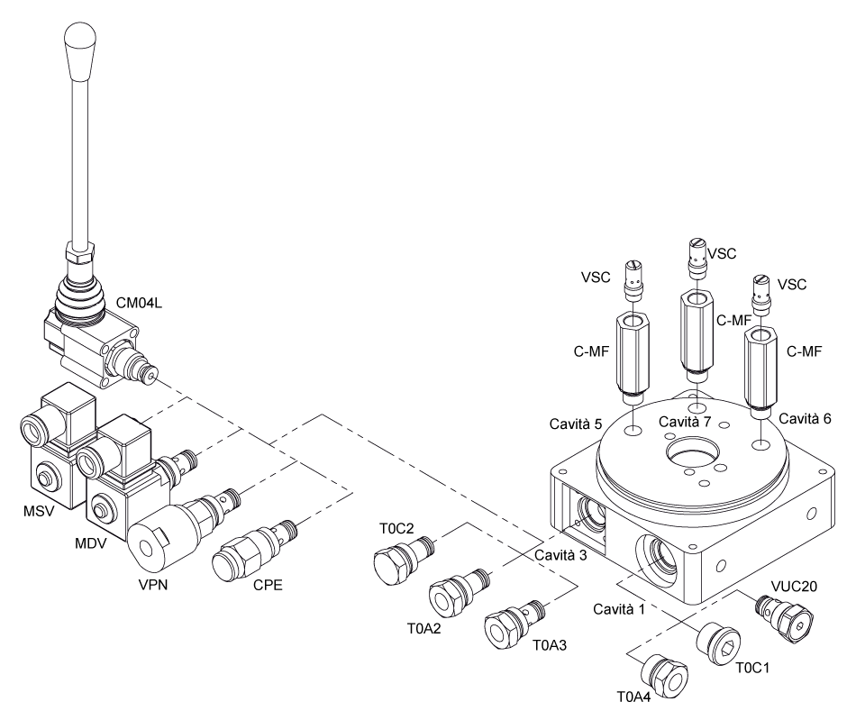
On this kind of central manifold is possible to mount the following valves:
Cavity 1: VUC20, T0C1, T0A4, CSB04
Cavity 2: VMDC35, T0VM
Cavity 3: T0A2, T0A3, T0C2, MSV, MDV, CPE, VPN, CSB04, PM02, CM04L
Cavity 5: VSC
Cavity 6: VSC
The central manifold not presents any sharp edge, all the corners were rounded, to prevent possible injury during the assembly of the manifold. The outer surface also reflects strict choices of roughness, presenting glossy and pleasant appearance.
To assemble the components on the G12, please refer to the installation instructions of the valves and solenoid cartridge, shown in the catalogue.
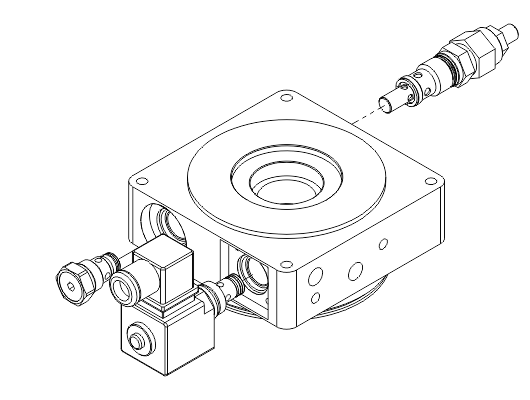
This central manifold is provided with four cavities that allow, if required in the hydraulic diagram, to accommodate both the pressure relief valve that check valve, that a derived solenoid valve but a control flow valve as well.
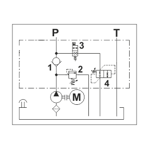
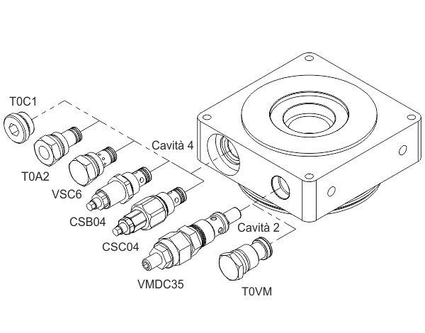
On this kind of central manifold is possible to mount the following valves:
Cavity 1: VUC20, T0C1, T0A4, CSB04
Cavity 2: VMDC35, T0VM
Cavity 3: T0A2, T0A3, T0C2, MSV, MDV, CPE, VPN, CSB04, PM02, CM04L
Cavity 4: T0C1, T0A2, VSC6, CSB04, CSC04
Cavity 5: VSC
Cavity 6: VSC
The central manifold not presents any sharp edge, all the corners were rounded, to prevent possible injury during the assembly of the manifold. The outer surface also reflects strict choices of roughness, presenting glossy and pleasant appearance.
To assemble the components on the G22, please refer to the installation instructions of the valves and solenoid cartridge, shown in the catalogue.
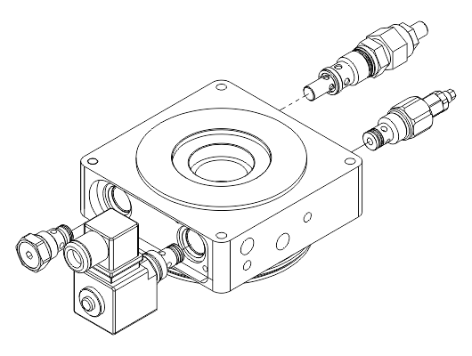
This central manifold is provided with five cavities that allow, if required in the hydraulic diagram, to accommodate both the pressure relief valve that check valve, that a derived solenoid valve but a control flow valve and an outlet pressure gauge as well direct on the manifold.
With this configuration it’s possible to realize simple hydraulic circuits, if the mini power pack has no blocks of the BL series, and more articulated, in the case of use of the latter, which allow modularly to be able to add a wide range of valves and solenoid valves.
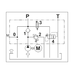
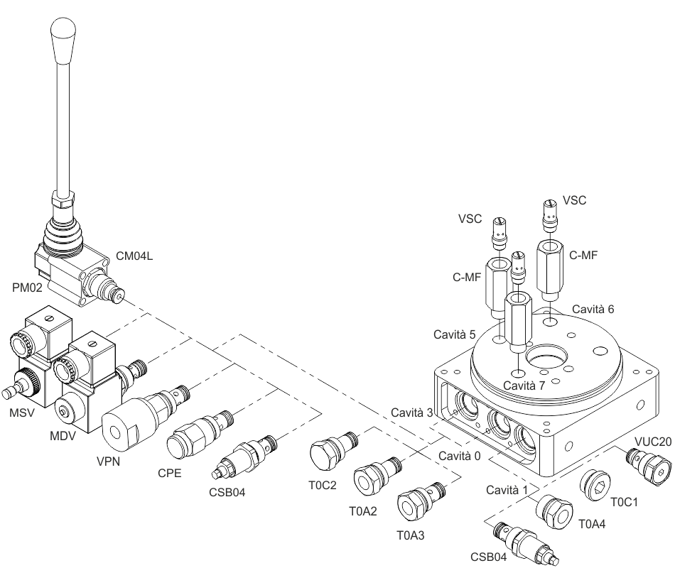
On this kind of central manifold is possible to mount the following valves:
Cavity 1: VUC20, T0C1, T0A4, CSB04
Cavity 2: VMDC35, T0VM
Cavity 3: T0A2, T0A3, T0C2, MSV, MDV, CPE, VPN, CSB04, PM02, CM04L
Cavity 4: T0C1, T0A2, VSC6, CSB04, CSC04
Cavity 5: VSC
Cavity 6: VSC
Cavity 7: VSC
Cavity 0: T0C2, T0A2, T0A3
Note: This kind of manifold can house anti-clockwise pumps only in presence of T0A3 and T0C2 plugs mounted into cavity 0. For complete circuits use clockwise pumps.
The central manifold not presents any sharp edge, all the corners were rounded, to prevent possible injury during the assembly of the manifold. The outer surface also reflects strict choices of roughness, presenting glossy and pleasant appearance.
To assemble the components on the G32, please refer to the installation instructions of the valves and solenoid cartridge, shown in the catalogue.